Berlin’s nightlife was an unforgettable experience during my study and work stint there, and I miss it. What stood out most to me were the clubs, which offered not only immersive music but also amazing light shows. That was sort of my inspiration for turning an unused room in my house into a mini dance floor.
After setting up and programming my first light shows with all the DMX fixtures I got off Amazon, I wanted to be able to control the light show wirelessly instead of through a USB cable connected to my laptop. That led to me making this Art-Net node.
If you want to control your DMX-capable lights wirelessly over Art-Net, this project is for you!
Table of Contents
- 🎯 Design & Goals
- 🔎 What is DMX for Lighting Control?
- 🔌 Before: Wired DMX Interface
- 🧐 Why a Raspberry Pi Pico W?
- 🛒 Part List
- 🌈 My Lighting Fixtures
- 🪛 Building the Pico Art-Net Node
- ⚡️ Creating the Circuit Board
- 🎁 Final Step: Putting it All Together
- 🧑💻 Programming Your Pico ArtNet DMX Node
- 🎉 Final Result
- 💡Programming the Lights
🎯 Design & Goals
- Able to control DMX lights wirelessly (over standard WiFi) from a computer, tablet, phone, or lighting console that supports Art-Net
- Output two, 512-Channel DMX Universes
- Harness the PIOs on the Raspberry Pi Pico for implementing the DMX protocol
- Inexpensive OLED display for debugging
- No RDM – For home & small dance floor setups where you can access the fixtures easily, this feature isn’t essential. Note: To add RDM support you can wire the Rx pin on the RS485 DMX modules to the Pico and use a DMX software library that supports it.
🔎 What is DMX for Lighting Control?
DMX (Digital Multiplex) is a digital protocol for controlling stage lighting and effects. It controls up to 512 channels per “universe”, with each channel representing a different light or setting. Devices are connected in a daisy-chain manner using specific cables, often with 5-pin or 3-pin XLR connectors. Each device is assigned a unique address, and the chain should be terminated with a terminator to prevent signal issues. Controllers, ranging from manual boards to sophisticated software, generate the DMX signal for the fixtures.
Art-Net allows DMX frames to be transmitted either by Ethernet or wirelessly over WiFi.
An Art-Net to DMX node converts those wireless packets into traditional wired DMX outputs. The Pico Art-Net node we are building can control two separate DMX universes, each with up to 512 channels.

🔌 Before: Wired DMX Interface
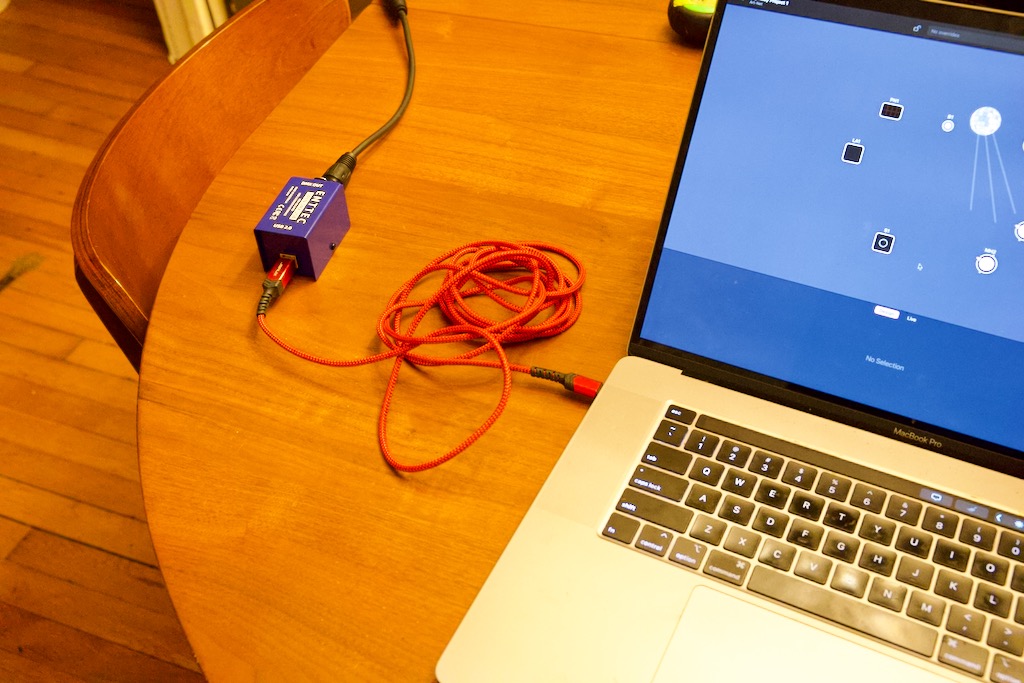
Before this project, I was using a wired Enttec Open DMX box which required a connection to the computer running the lighting software.
After this project, I’ll be able to control the lights wirelessly over WiFi. The node we are building will translate the DMX over WiFi (Art-Net) into traditional wired DMX outputs.
🧐 Why a Raspberry Pi Pico W?
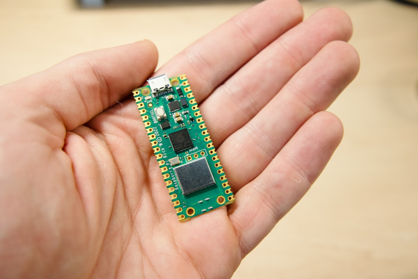
This project uses a low-cost Raspberry Pi Pico W microcontroller. We need to use the “W” or “WH” version of the Pi Pico because the W version has WiFi.
Raspberry Pi Pico’s Best Feature: The PIOs
There are other Art-Net/DMX node articles out there that use alternative microcontrollers like the ESP32 or the ESP8266. The PIOs on the Raspberry Pi Pico sold me on using a Raspberry Pi Pico instead of an ESP32, ESP8266, or other low-cost microcontroller.
The library we will use (Pico-DMX) for DMX transmission uses the PIOs to implement the DMX protocol.
The PIO (Programmable Input/Output) is one of the standout features of the Raspberry Pi Pico’s RP2040 microcontroller. It’s essentially a versatile hardware interface that’s specifically designed for custom peripheral support. Here’s what the PIO is for:
- Custom Protocols: One of the main reasons the PIO exists is to allow users to implement custom or unusual communication protocols, like DMX512, that might not be natively supported by the RP2040’s hardware.
- Offloading CPU: Tasks that may require precise timing or quick response times can be offloaded to the PIO, freeing the main CPU cores from having to manage these tasks in real-time.
- Flexible I/O Operations: PIOs allow the RP2040 to handle a wide range of I/O operations, extending the possibilities beyond standard GPIO operations.
- Parallel Processing: The PIO allows you to run operations in parallel with the main CPU cores, which is beneficial for applications that need to manage multiple tasks simultaneously. The Pico-DMX library supports 8 parallel outputs, each of the two PIOs handles 4 outputs.
- Reducing Latency: For time-sensitive operations, going through the CPU can introduce unwanted latency. PIOs can be programmed to handle such operations directly, providing faster and more consistent response times.
- Efficient Power Management: Using PIO for certain tasks can be more power-efficient than constantly waking up a CPU core, which can be especially beneficial for battery-operated devices.
- Versatility: Even for standard protocols (like SPI or I2C), if you need them to operate in a slightly non-standard way, PIOs can be incredibly useful. They can be programmed to precisely match the requirements of almost any digital interface.
The PIO is a set of programmable state machines. The RP2040 on the Pico provides two PIO blocks, each with four state machines. Each of these state machines can be programmed to manipulate GPIOs and transfer data. The real power of PIO comes from its ability to execute programs to achieve the desired I/O behavior. These programs are written in an assembly-like language tailored specifically for the PIO.
For many users, the existing hardware peripherals on the RP2040 will suffice for their projects. However, for those who need something a little different, or those looking to push the boundaries of what’s typically possible with a microcontroller in this price range, the PIO offers an unprecedented level of flexibility.
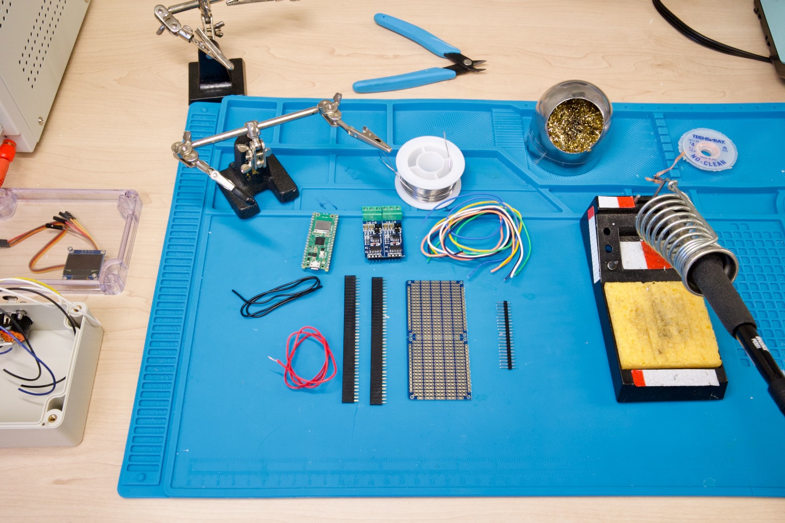
🛒 Part List
Components
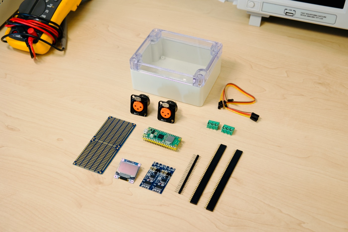
The first thing on your list should be a Raspberry Pi Pico W (or WH). The W stands for wireless/WiFi.
The Raspberry Pi Pico W and WH are the same, but the WH comes with headers pre-soldered which makes them cost a bit more but reduces the amount of soldering required. Since you’re soldering anyway and buying headers, it’s just a matter of personal preference if you want to buy a W and solder the headers yourself or if you want to go with a Pico WH.
You can buy a Pico W from official authorized sellers or from Amazon. At the time of writing, the Picos can only be found on Amazon and are priced a bit more expensive.
Pi Pico W:
or, a Pi Pico WH:
Other Parts:
- PCB Prototype Strip Board With Power Rails
- TTL-to-RS485 Modules (We need two modules)
- Header Strips – Assortment. They are handy for mounting boards like the Pi Pico W and the RS485 modules in a way that allows you to easily remove or swap them.
- Screw Terminal Block Kit – You need two 3-terminal blocks
- Plastic Project Enclosure
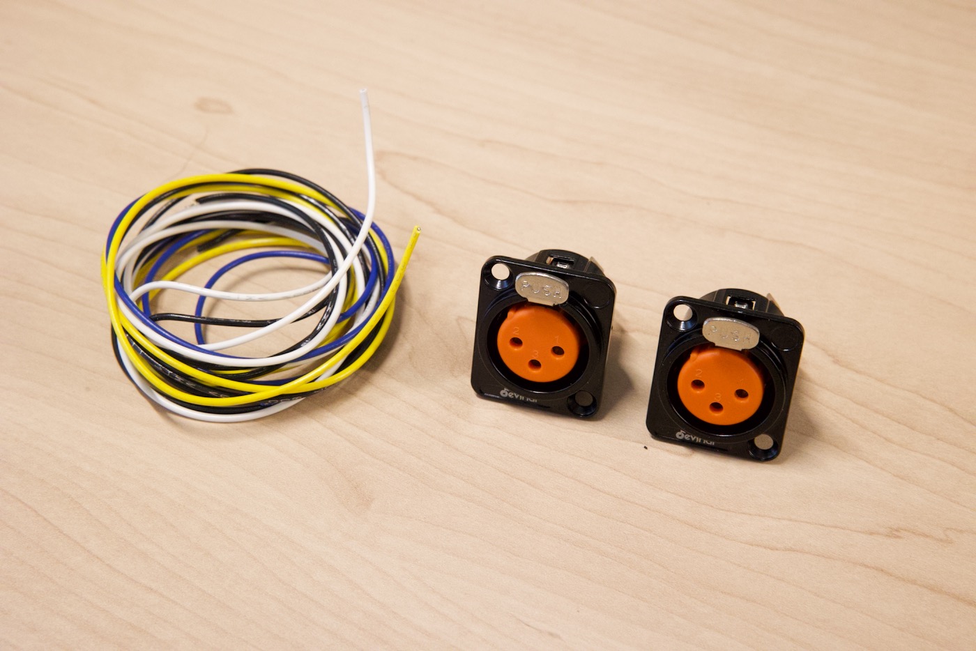
- XLR Female Panel Mounts
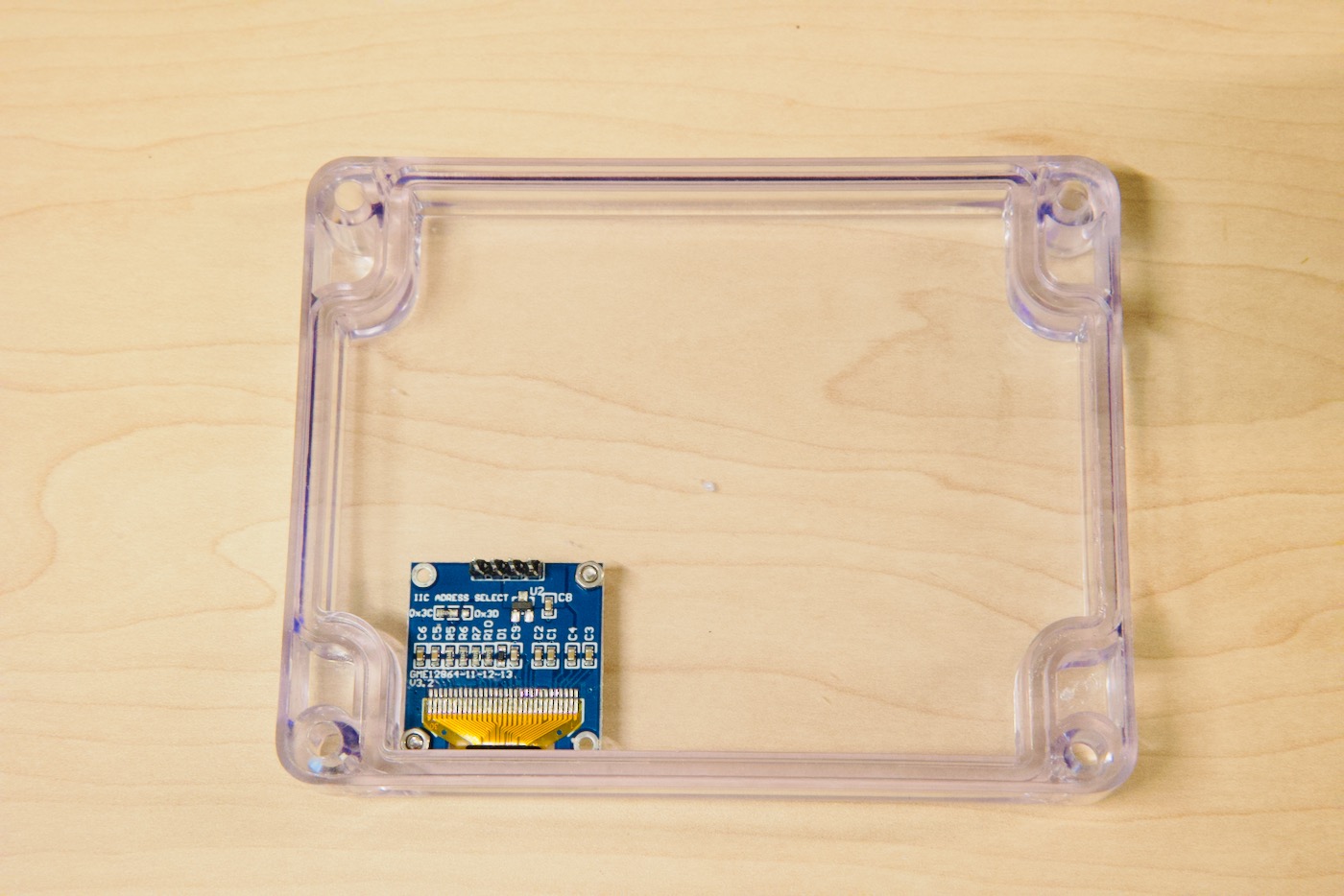
- .96″ OLED Display (Recommended)
- Ribbon Jumper Cables (Used for OLED Display). If you have four female-to-female jumper cables (or want to solder plain wires), you don’t strictly need this.
- Mounting Tape (Optional – for securing PCB to Bottom of Enclosure)
- 22 Gauge Solid Wire (Or Breadboard Jumper Wire). I also used Stranded Wire (For connecting the XLR Jacks to the screw terminals) but using solid wire is also fine.
- Packing tape or small screws (Optional) for mounting OLED inside the project enclosure. I used M2 screws with a length of 10mm. Here’s a screw kit that’s handy for projects like this one. It comes with nuts and Allen wrenches.
Tools
If you do electronic projects, you could have all of these already in your home workbench:
- Cordless drill (such as this Ryobi one or the Milwaukee one)
- Soldering Iron
- Solder (I use traditional Tin/Lead Solder)
- Multimeter such as the Fluke 117 (There are cheaper alternatives on Amazon)
- Step Drill Bits – My new favorite way to drill clean holes in thin plastic or sheet metal!
- Phillips Screwdriver
- Precision Screwdriver Set
- Flush cutters
Custom PCB, Stripboard, Breadboard?
Stripboards are a great middle-ground between breadboards, which offer quick prototyping without soldering, and custom-made PCBs, which are more professional and suited for final products or larger production runs. They allow for relatively permanent setups compared to breadboards and are ideal for creating one-off projects or prototypes.

The OLED Display
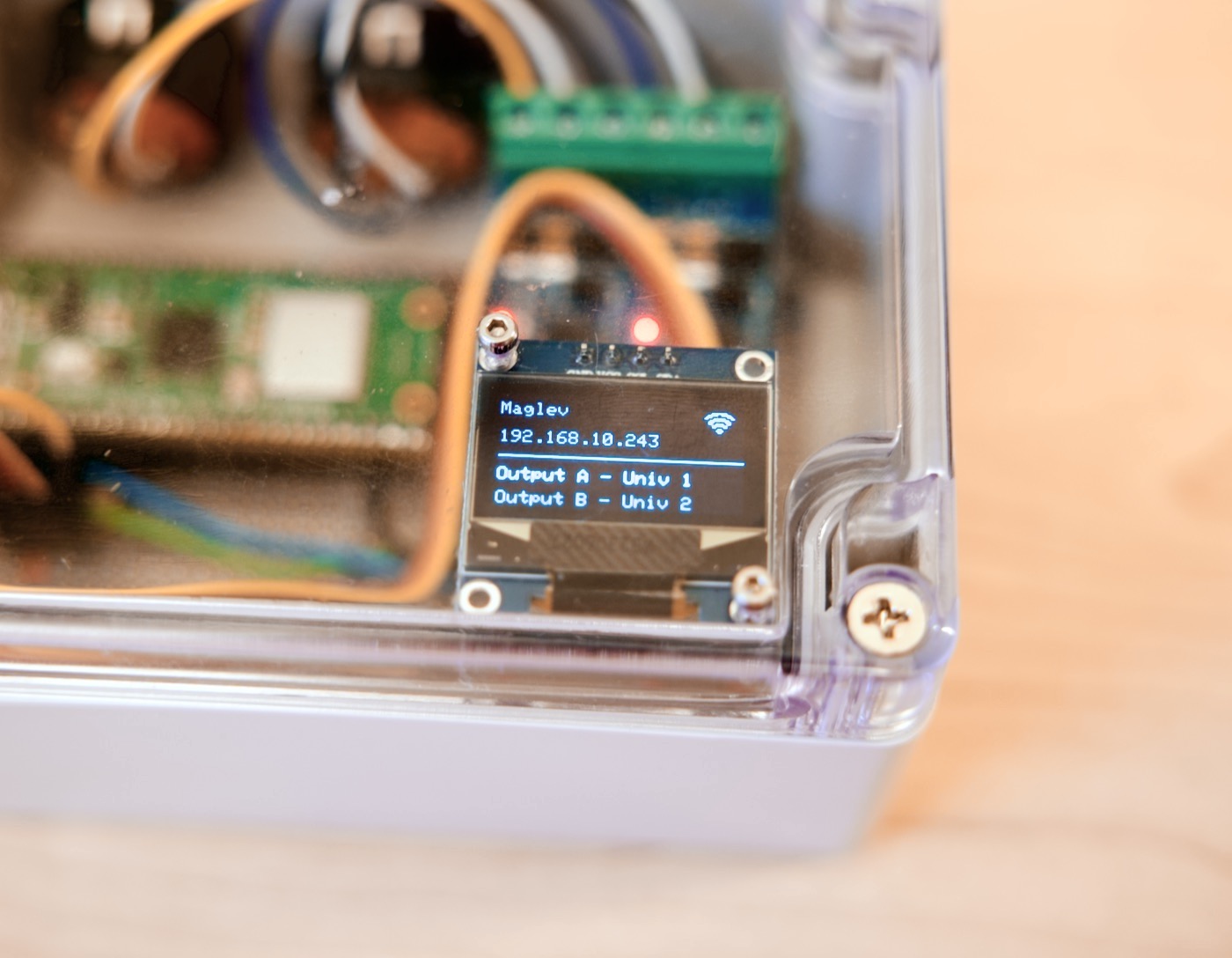
The OLED is optional and could be replaced with a status LED or two to help debug. Since these small OLED displays are only a few dollars, and easy to connect, I like including them on my hobby projects. The only downside really is that it’s a bit more code to get relevant info displaying, but I find it worth the time. I use it to self-document and display config info. On this project, I can see whether it’s connected to WiFi and which universes are mapped to the two outputs (A and B).
The OLED code is in its own file (OLED.h) and you can remove this file and comment out the invocations in the main .ino file if you don’t want to use an OLED display.
In addition to the OLED for debugging, the two TTL-to-RS485 modules have status LEDs to show whether they are transmitting (TX) or receiving (RX).
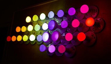
🌈 My Lighting Fixtures
You’ll want at least one DMX-capable lighting fixture and a 3-Pin DMX cable. Cables can be found on Amazon and vary widely in price and length. A terminator isn’t strictly needed (in my experience), but it’s best practice to have one on the last DMX fixture in the chain.


DMX-capable fixtures are plentiful, and some can be found for less than $30. I’d recommend starting with a few and building up from there.
- RGBW Pinspot with Sound Activated mode – I use this DMX spot to illuminate my mirror ball 🪩


- Moving Head Lights 8 Gobos 8 Colors 11 Channels 25W Spotlights DMX 512 with Sound Activated. Sold as a pair!

- Ehaho DJ Laser Party Lights, 3D Animation RGB Lazer Stage Lighting, DMX512 Music Sound Activated

- DMX Spider Light

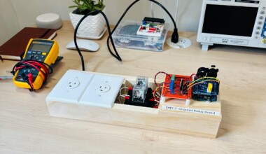
- My Custom-Built DMX 2-Channel Power Strip
I made a 2-channel DMX switch out of relays and an old Arduino that turns on/off a small second mirror ball light and a UV Blacklight Bar. This allows me to control two “dumb” fixtures in addition to the other DMX fixtures I purchased.
🪛 Building the Pico Art-Net Node
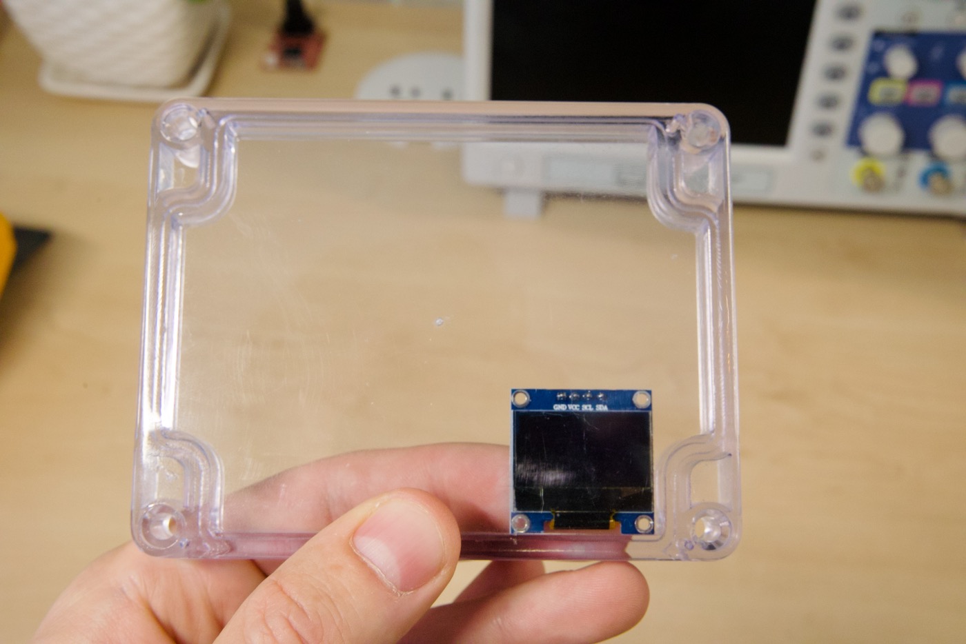
Mounting the OLED Display
Let’s mount the OLED display to the top of the case.
First, position it with your hands and mark the holes so we can drill holes for the mounting screws.
Drill at least two holes for mounting the display:
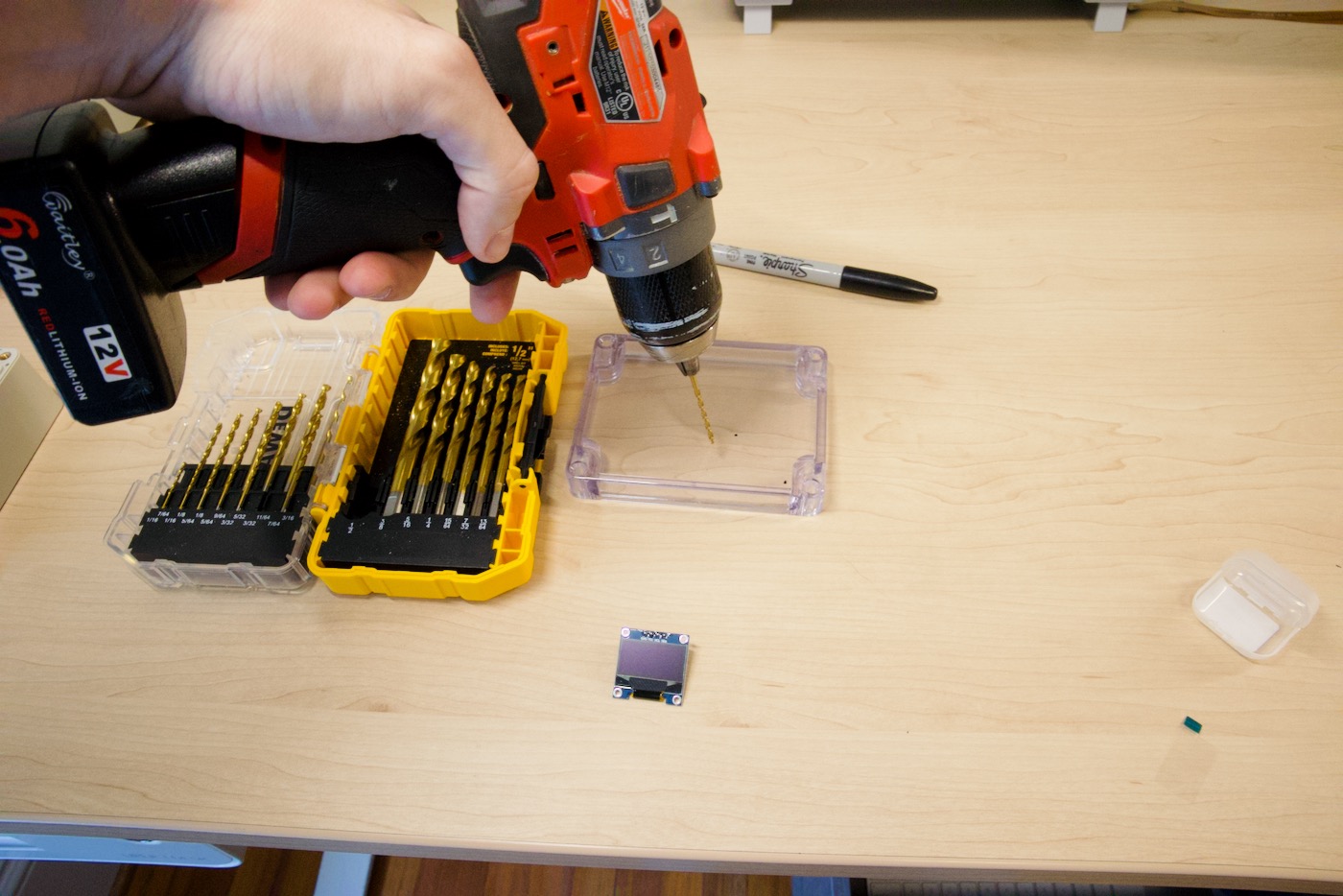
Screw in the OLED display to the underside of the top of the enclosure with the screen facing out:
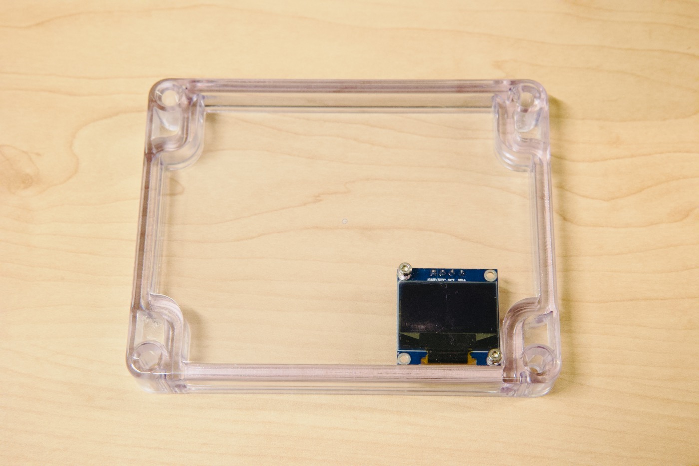
Back View:
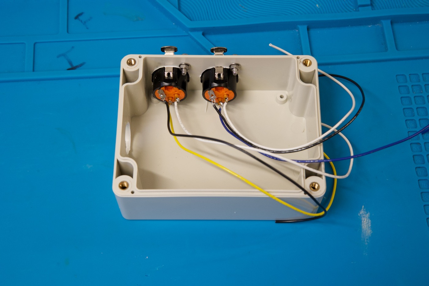
Soldering the XLR Jacks
Next, we’ll prep the DMX output jacks by soldering some stranded wire to each of the three XLR jack pins.
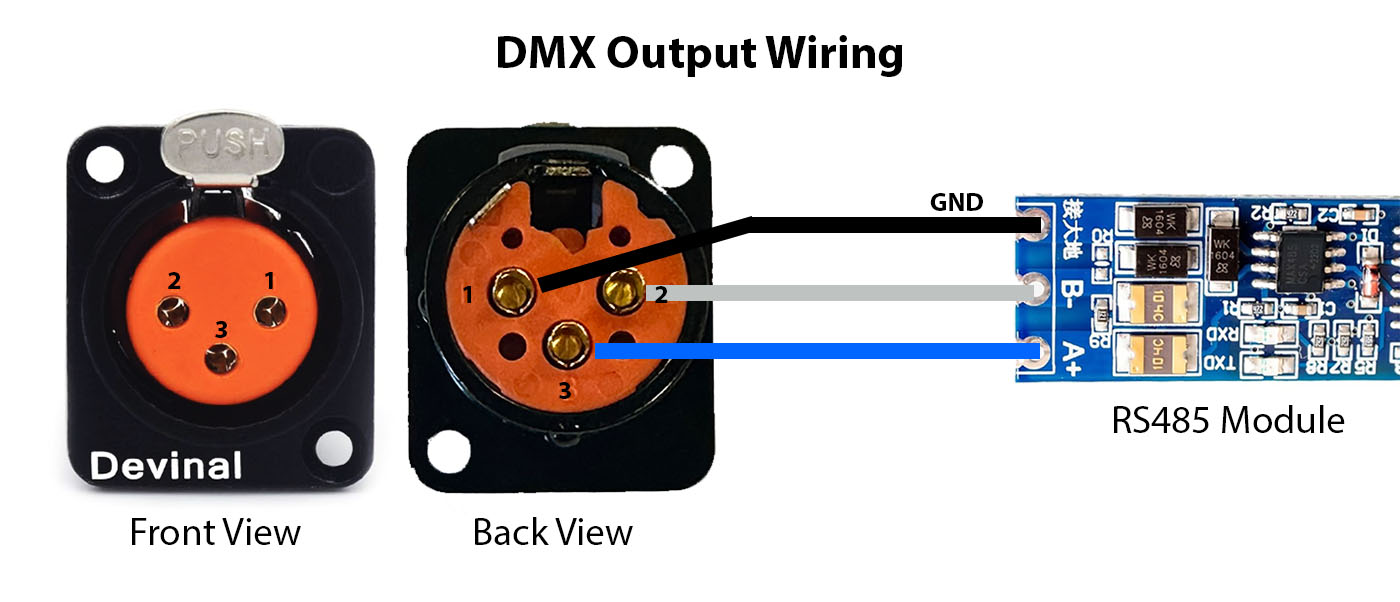
Solder the wires to the rear of the jacks:
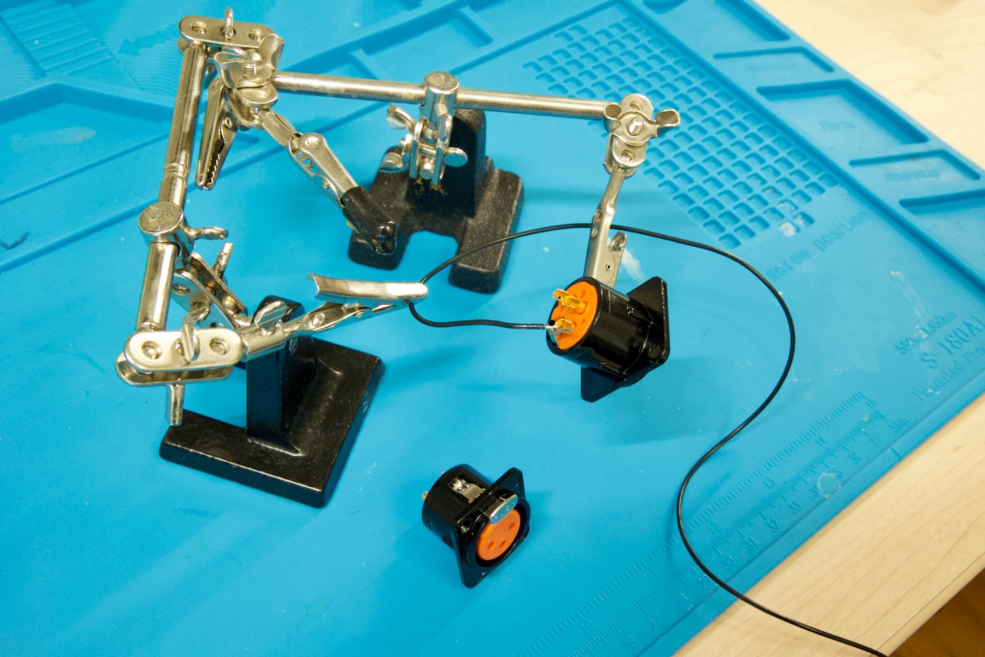
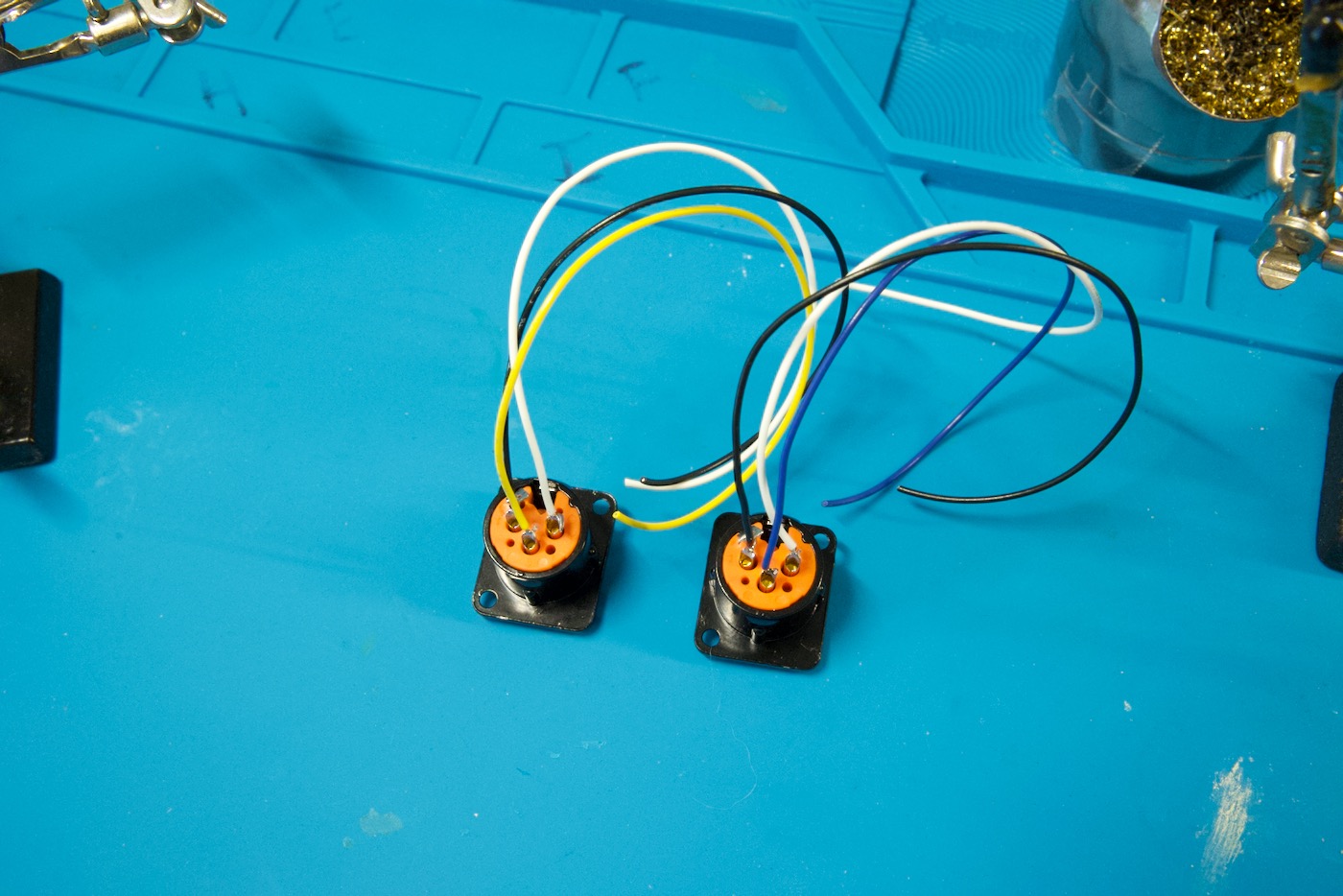
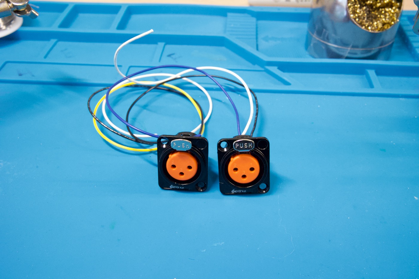
Done! Now we can set these aside and continue preparing the enclosure.
Drilling Holes for Power and DMX Outputs
We’ll need three holes in the enclosure – Two for the DMX/XLR jacks (which we’ll drill now) and another for the power Micro USB cable. You can drill the one for the power cable later once the PCB is ready and you can mark where the cable will need to go out through the enclosure.
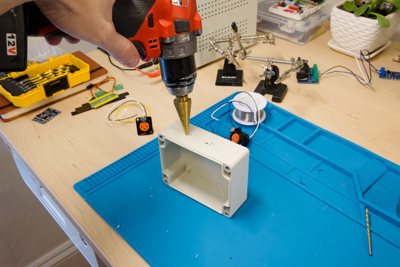
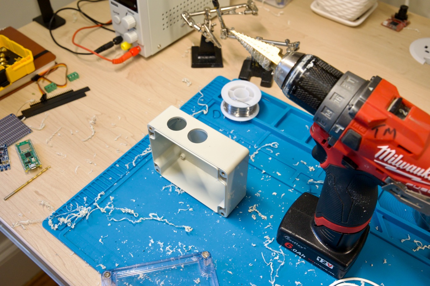
The holes need to be slightly larger than 7/8 of an inch. What’s great about using a step drill bit is you can slowly enlarge the hole until everything fits just right.
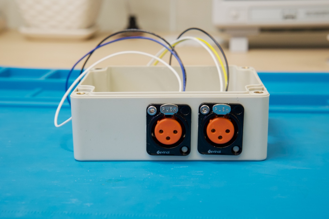
Mounting the DMX/XLR Jacks to the Enclosure
Each XLR Jack has two screw holes for mounting to a panel. I just put one screw in each. Hot glue or epoxy could also be used as an alternative to fix the jacks to the case.
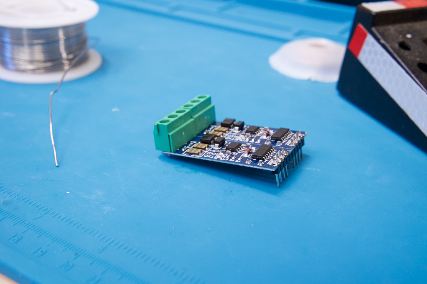
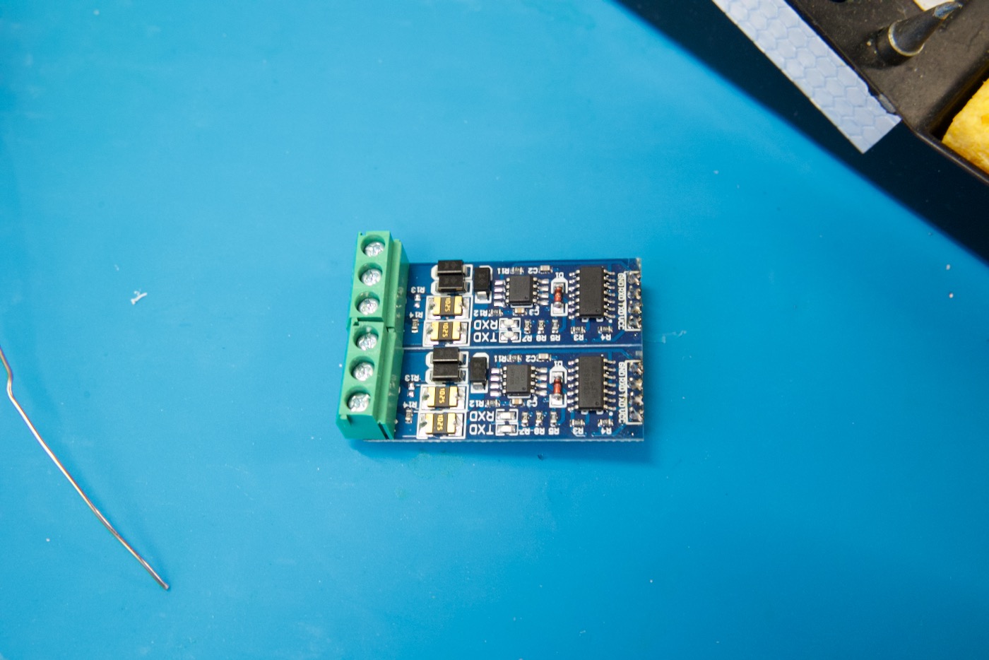
Assembling the TTL to DMX (RS485) Modules
The TTL-to-RS485/DMX modules need headers and screw terminals.
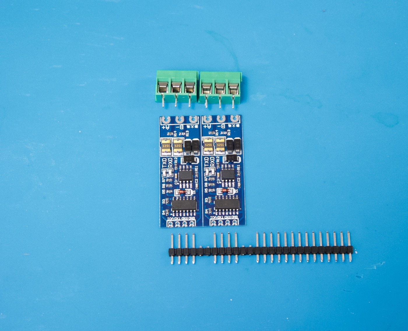
Start by soldering on the screw terminals:

Then solder on the headers:
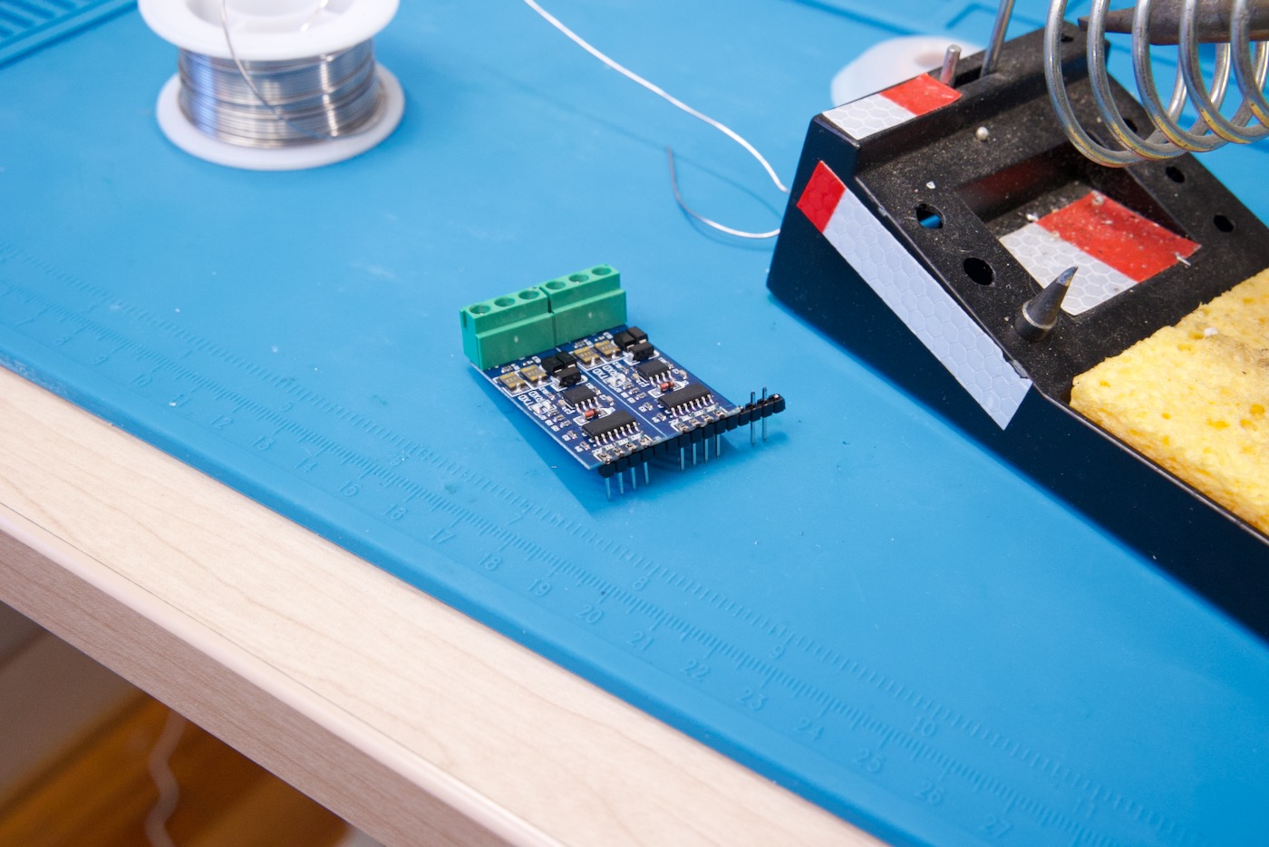
Trim off the excess headers if needed and you’re done preparing the TTL-to-RS485 modules:
⚡️ Creating the Circuit Board
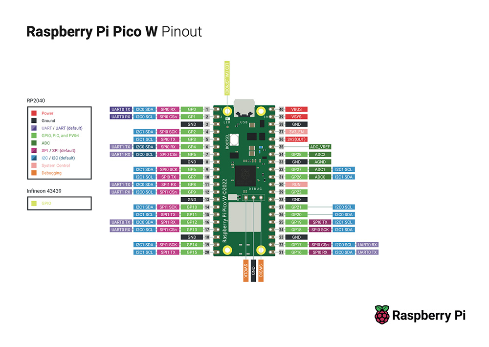
Schematic – Wiring the Pico to the RS485 Modules & Display
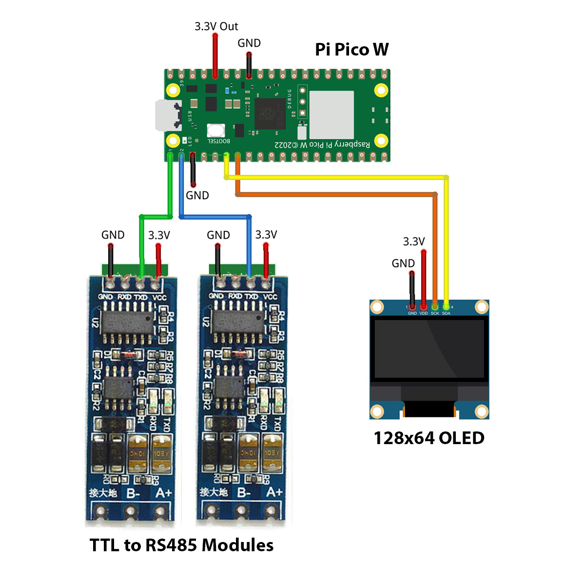
| Raspberry Pi Pico W | SSD1306 OLED 128×64 |
| Pin 6 – GP4 (I²C0 SDA) | SDA |
| Pin 7 – GP5 (I²C0 SCK) | SCL |
| Pin 36 – 3.3V | VCC |
| Pin 3, 8, 13, 18, 23, 28, 33, or 38 – GND | GND |
| Raspberry Pi Pico W | TTL to RS485 Modules |
| Pin 1 – GP0 | TXD Pin on Module #1 (Output A) |
| Pin 2 – GP1 | TXD Pin on Module #2 (Output B) |
| Pin 36 – 3.3V | VCC |
| Pin 3, 8, 13, 18, 23, 28, 33, or 38 – GND | GND |
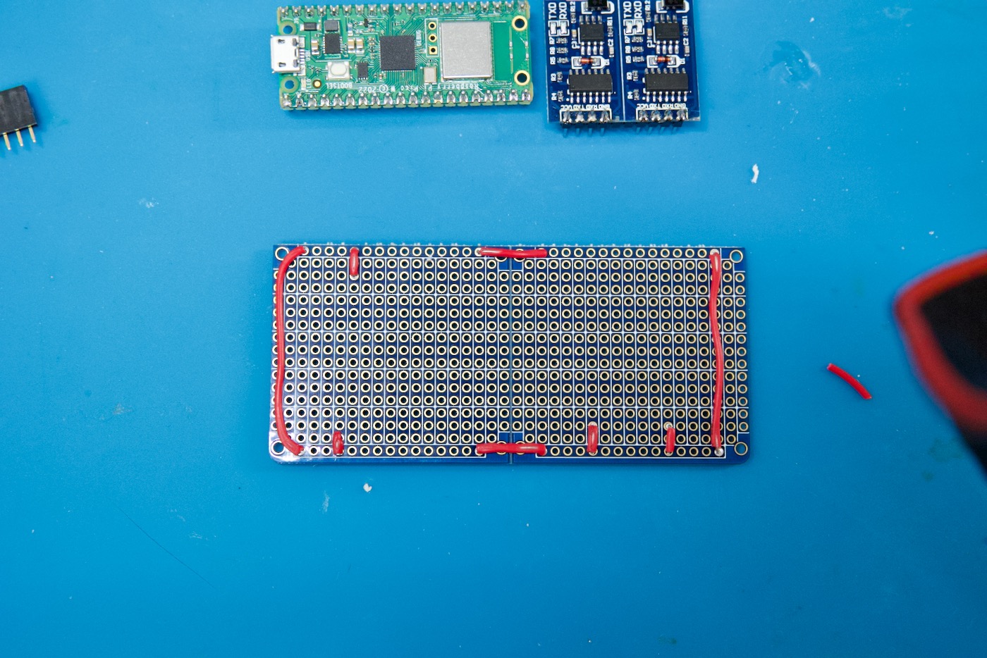
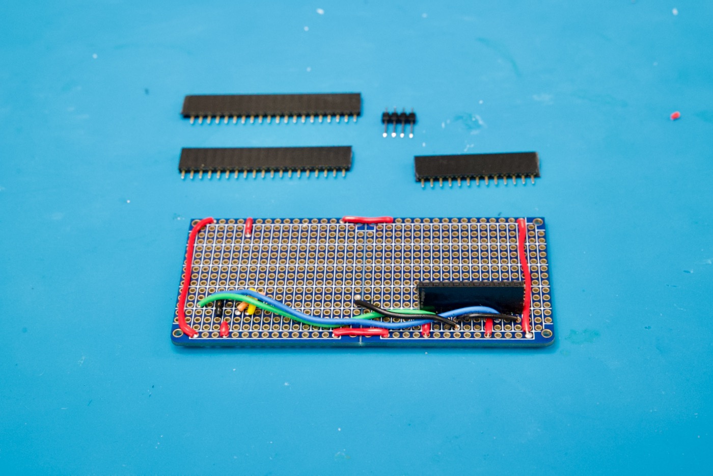
Soldering the Circuit Board
First, connect the rails (strips) that surround the stripboard to create a 3.3V power rail ring so power is accessible from everywhere:
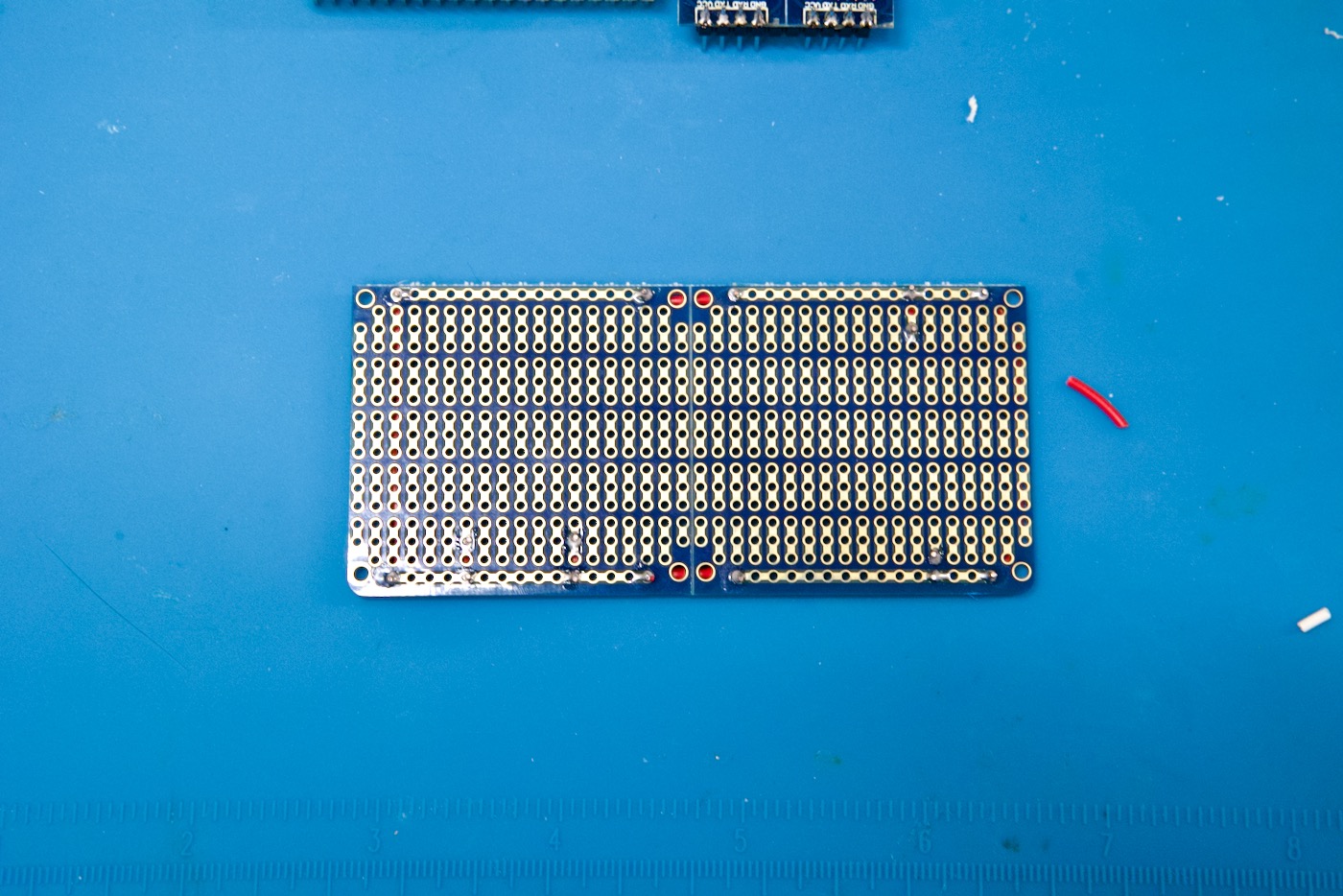
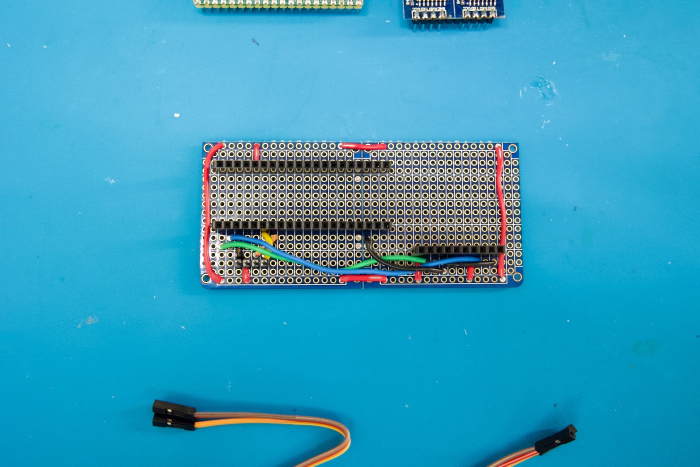
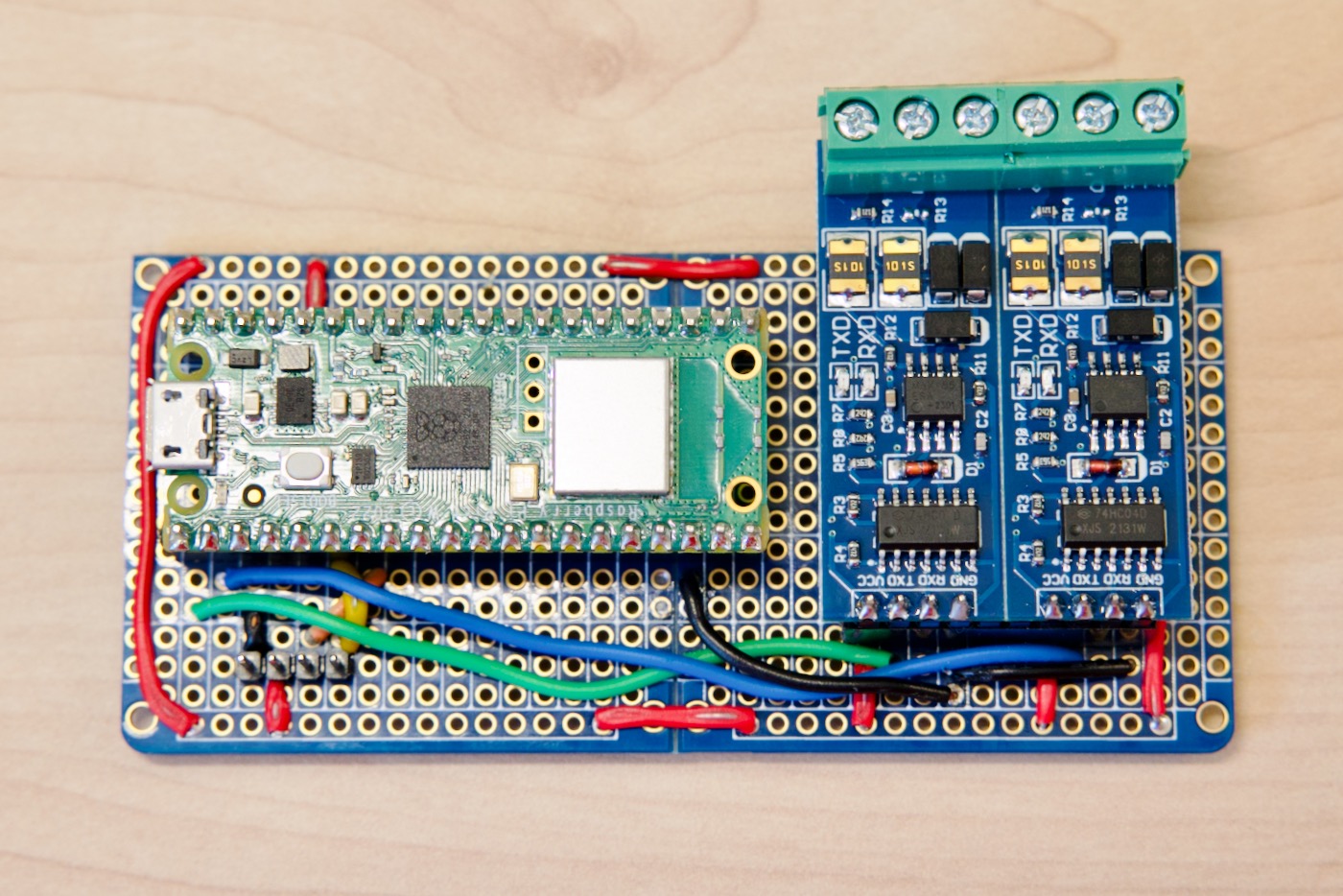
Next start adding the other connections and headers:
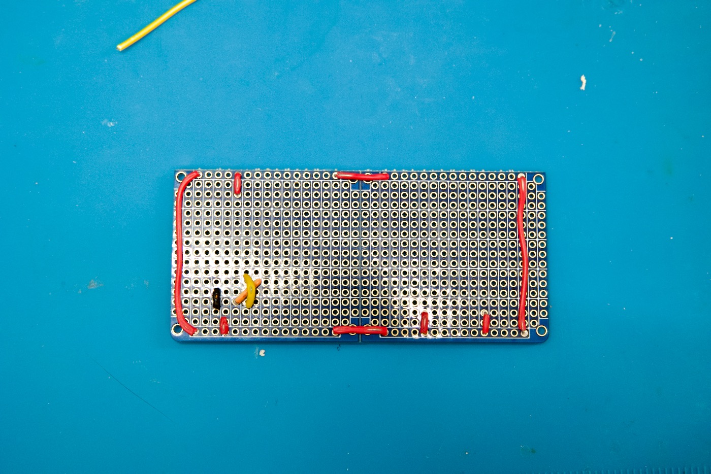
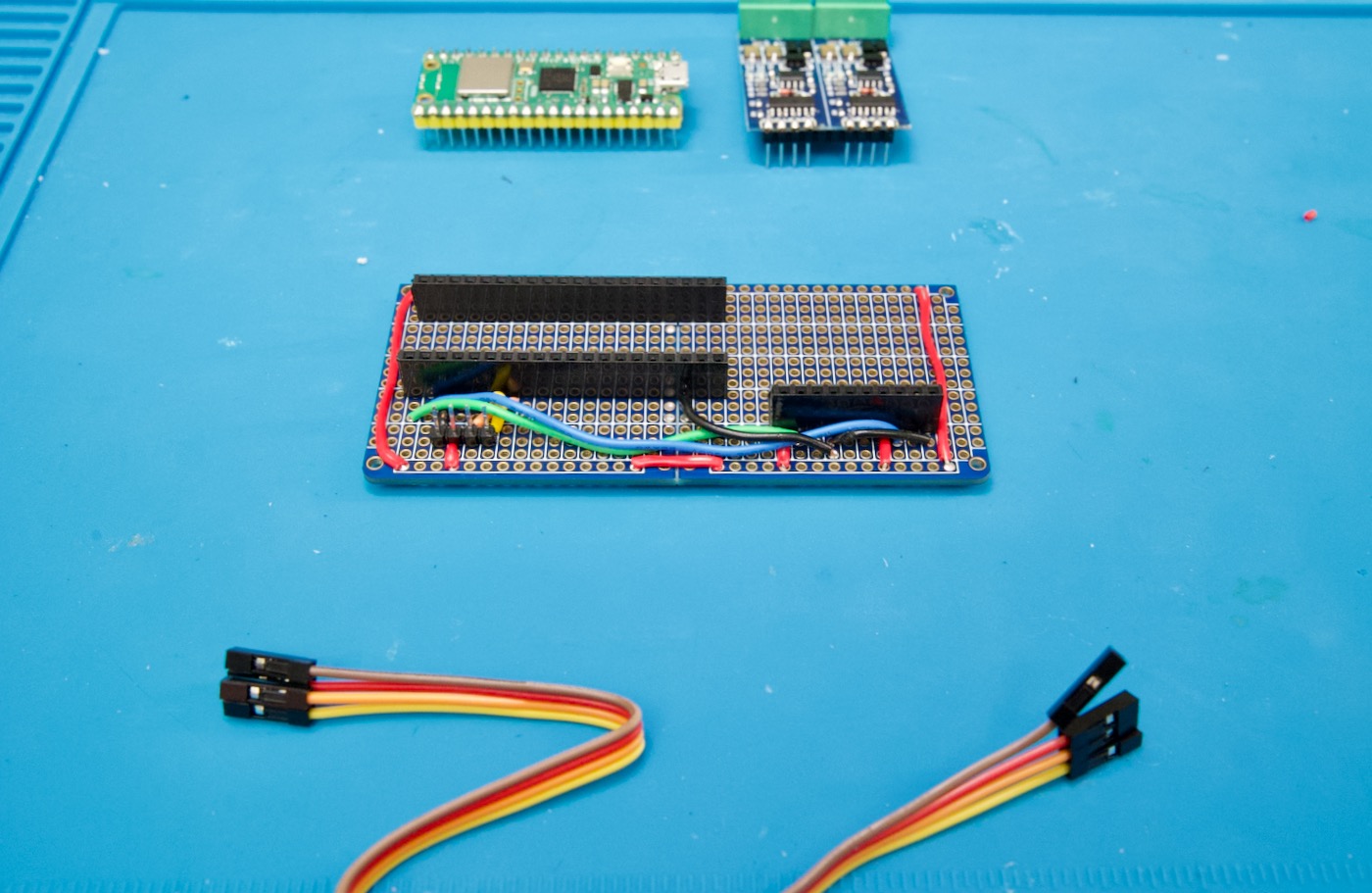
After adding the rest of the headers and the 4-pin header for the OLED cable, it should look like this:
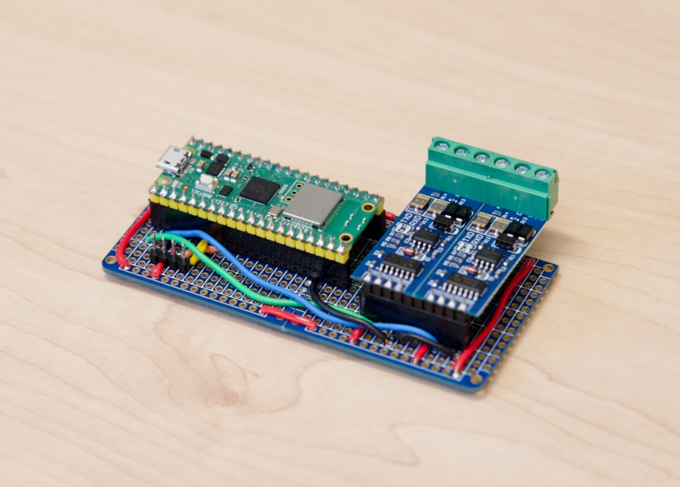
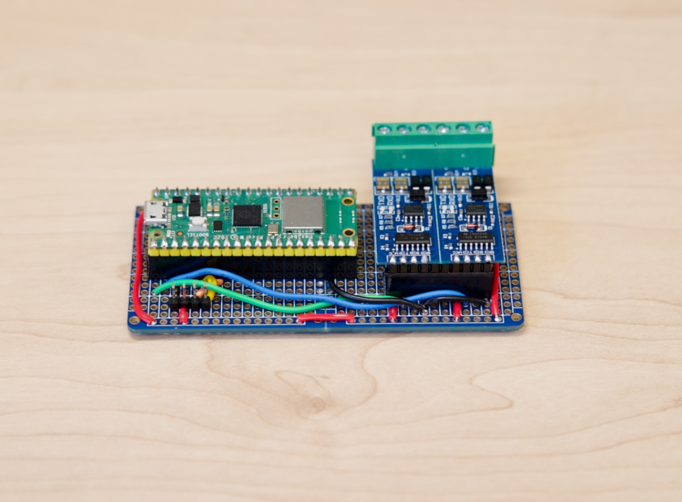
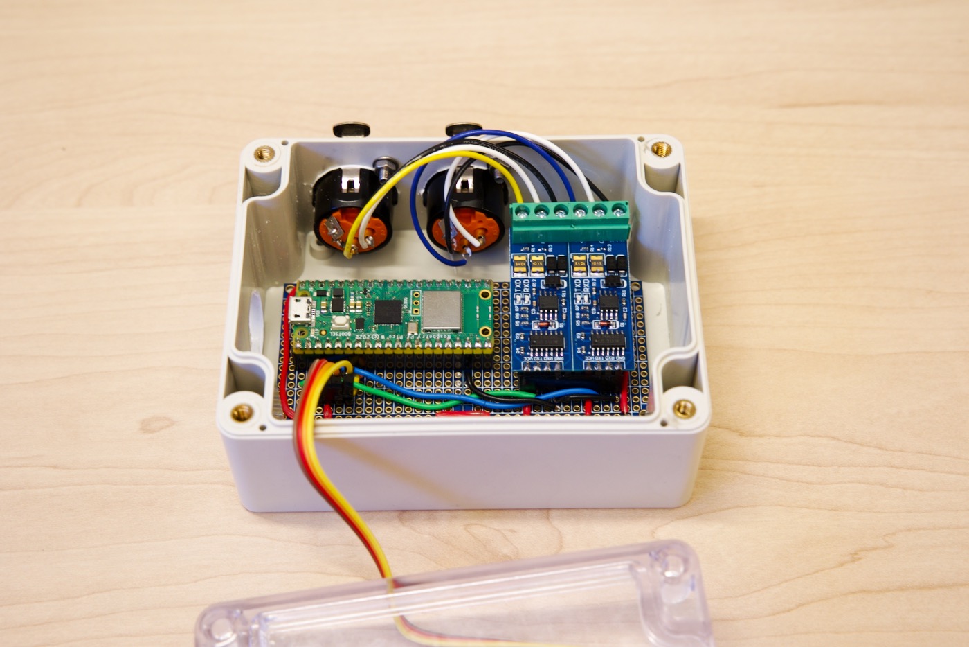
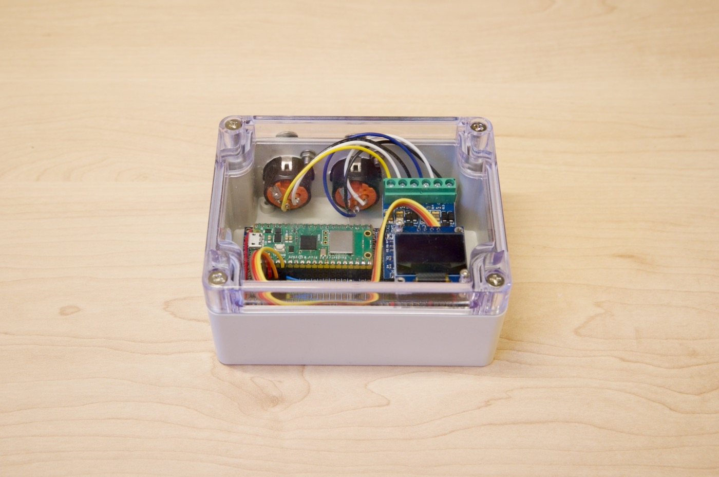
Inserting the Pico W and the RS485 Modules
Install the Pi Pico W and the two TTL-to-RS485 modules you have prepared:
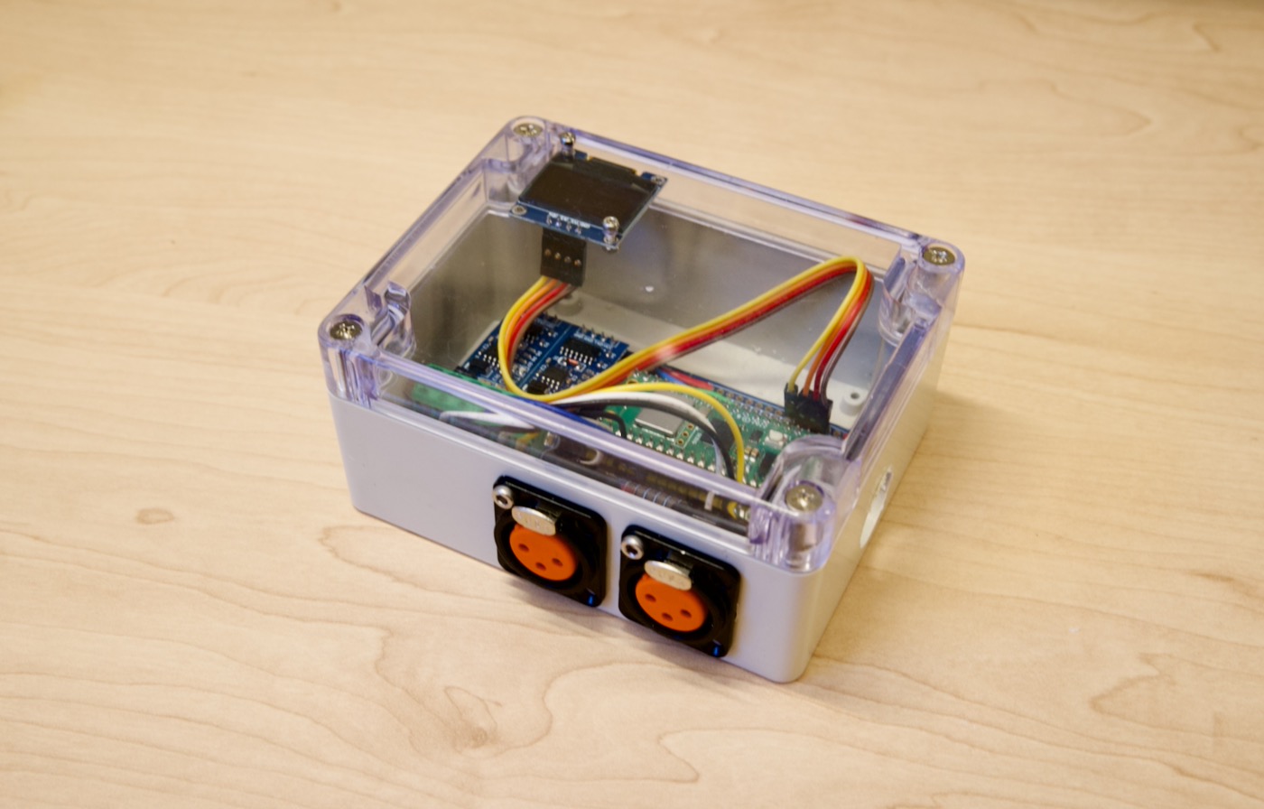
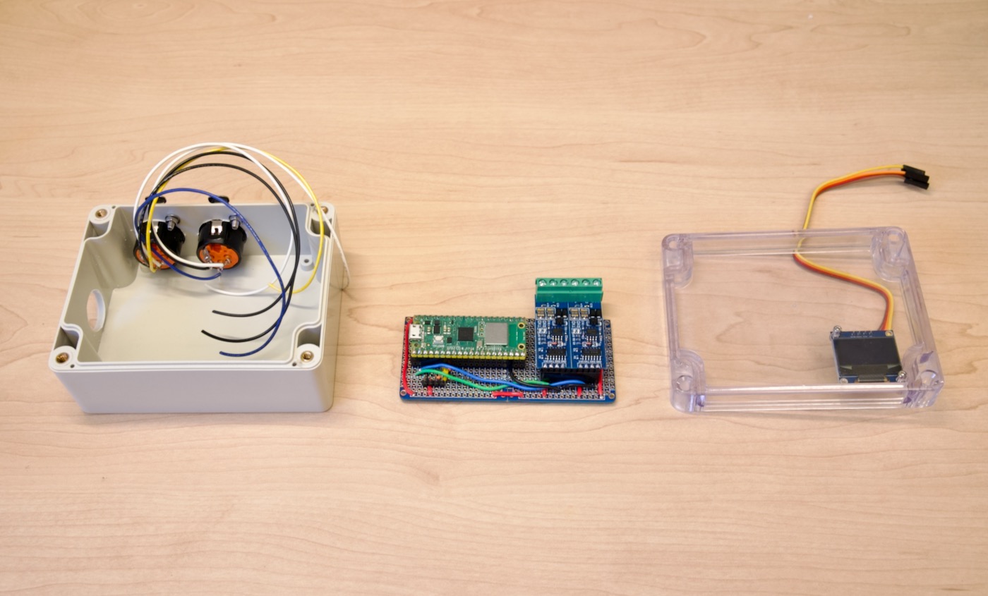
🎁 Final Step: Putting it All Together
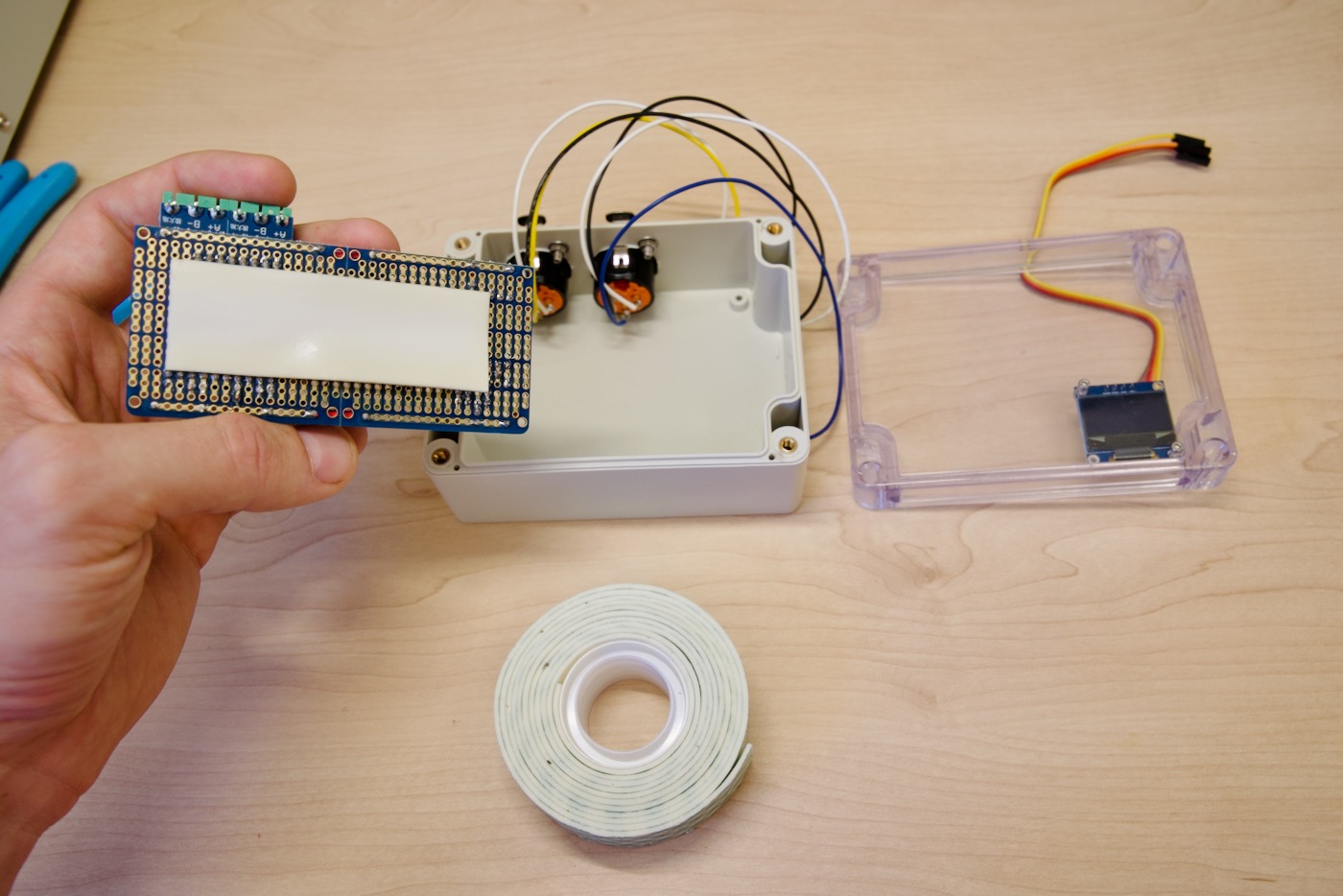
In this step, we’re going to mount the circuit board inside the enclosure and attach the DMX jacks and the OLED display.
Add mounting tape to the bottom of the PCB:
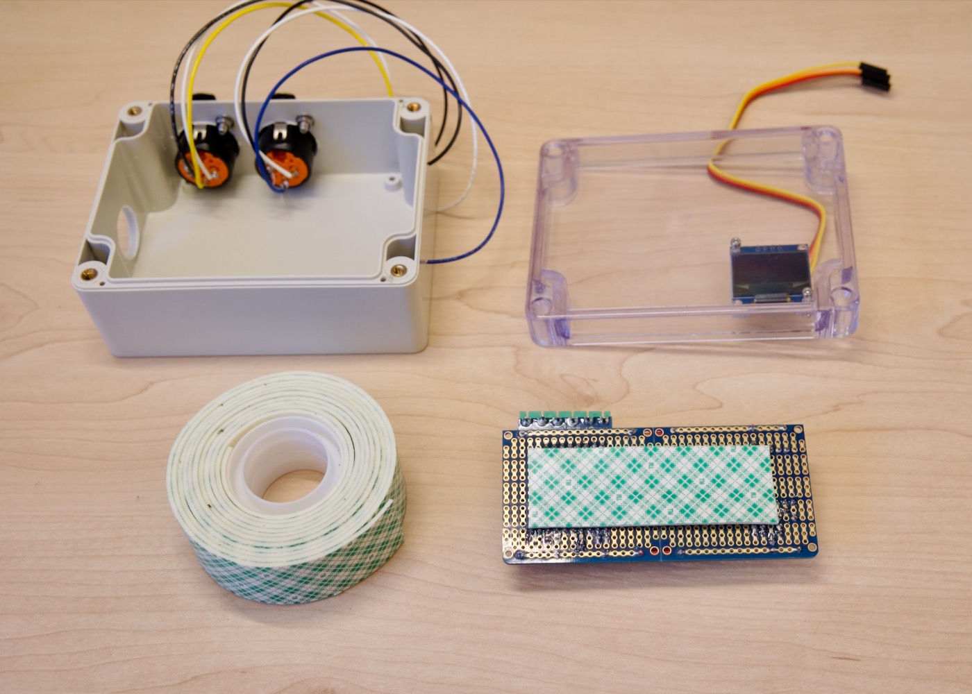
Install the circuit board onto the bottom of the case:
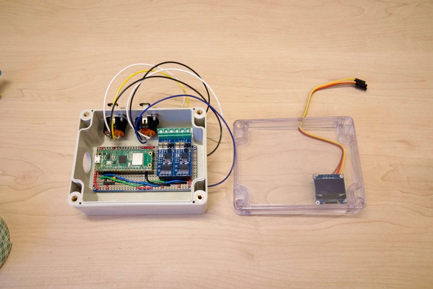
Connecting the Wires
Next we’ll connect the DMX/XLR jacks to the two TTL-to-RS485 modules:

Wire the DMX jacks to the RS485 screw terminals:
With the OLED connected:
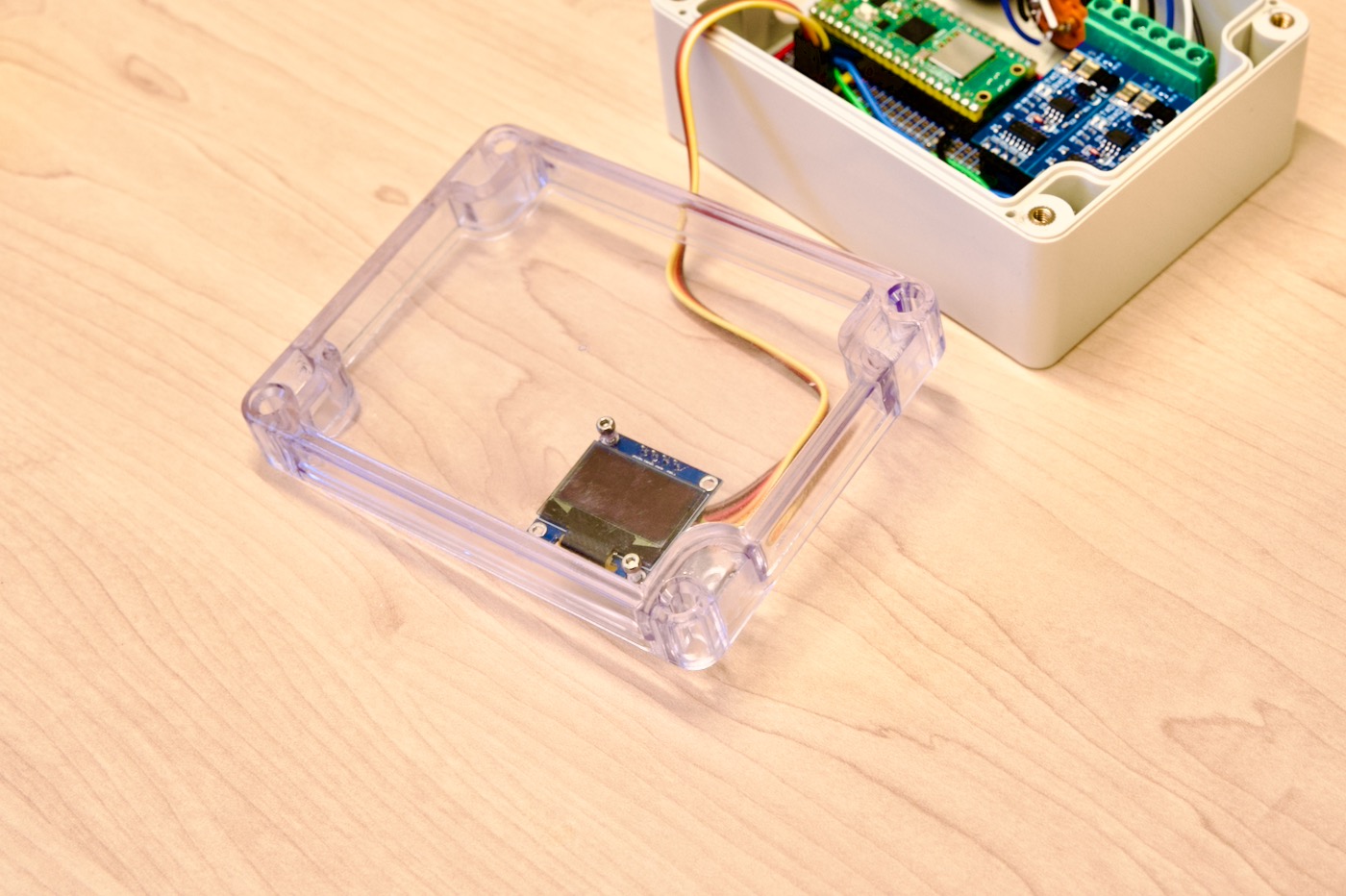
Finally, screw in the four screws to attach the clear top of the case to the base:
🧑💻 Programming Your Pico ArtNet DMX Node
Now that we’re done with building all that’s left is to add our code!
Why C++ instead of MicroPython / CircuitPython?
I’m using C++ because the Pico-DMX library, which leverages the power of the Pi Pico’s PIOs, is written in C++. If you’re interested in a MicroPython version, let me know in the comments.
Setting up the Arduino IDE
We’ll use the Arduino IDE for our C++ code. Installing support for the Pico W and other RP2040 boards is a fairly straightforward process.
First, we’ll add the RP2040 board manager URL in the Settings. Go to the Arduino Settings/Preferences which on a Mac is under Arduino IDE → Settings
Copy the following URL:
https://github.com/earlephilhower/arduino-pico/releases/download/global/package_rp2040_index.json
Then, paste that URL in the Additional Board Manager URLs field. If you already have a URL there, such as one for the ESP32 and/or ESP8266 Boards, you’ll want to keep those too.
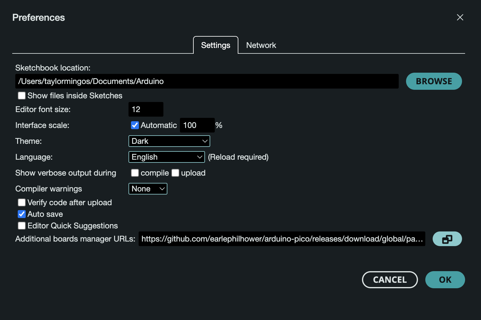
Clicking the button to the right of the Additional Boards Manager URLs field opens up a box that is easier to work with if you have multiple URLs:
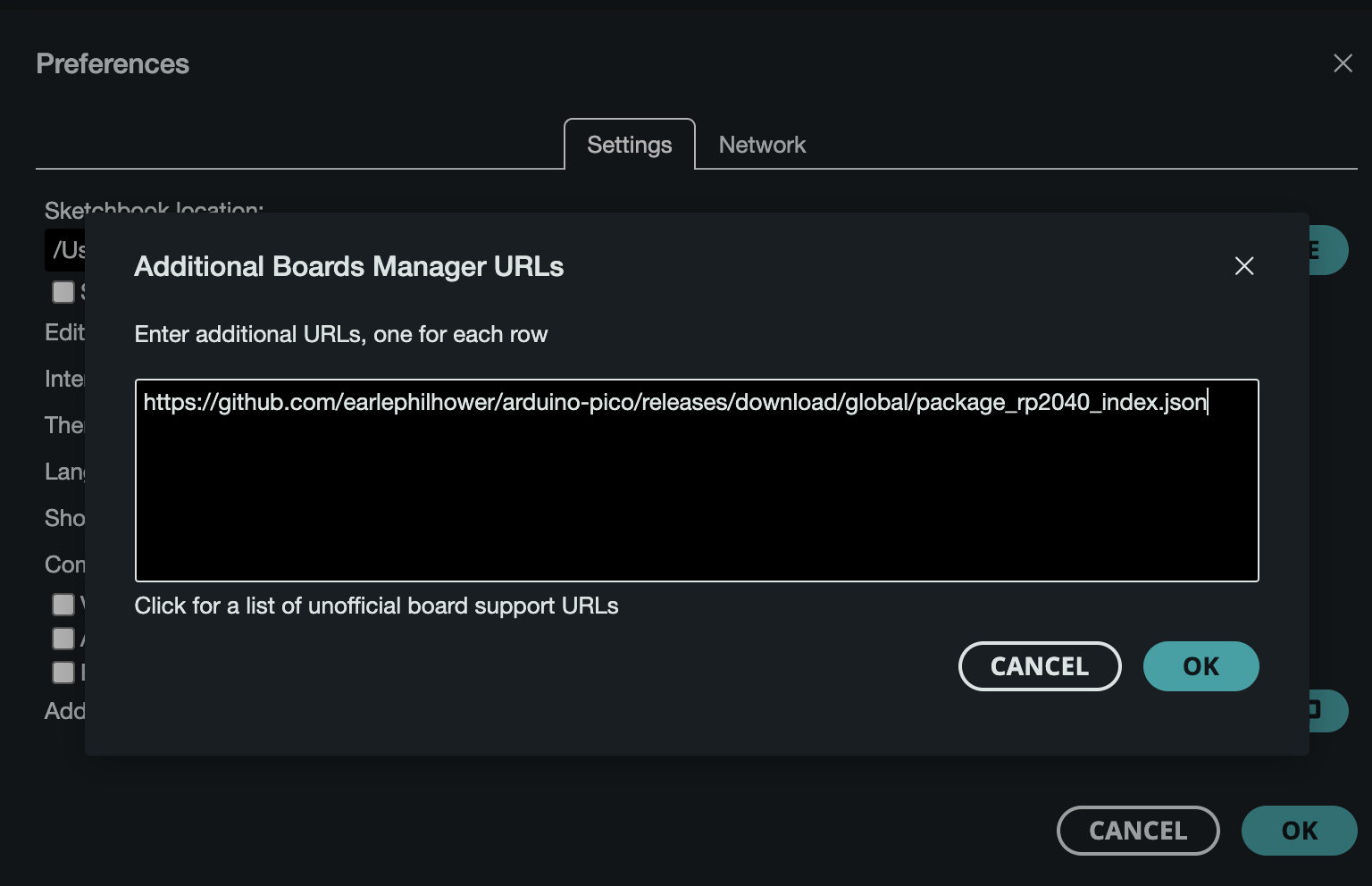
Finally, exit the Settings window and go to Tools → Board → Boards Manager. Scroll down until you find Raspberry Pi Pico/RP2040 and click on Install.
Installing the Dependencies
Be sure to install the following dependencies under Tools → Manage Libraries:
Dependencies:
- ArtnetWifi by Nathanaël Lécaudé, Stephan Ruloff (Tested with 1.5.1)
- Pico-DMX by Jostein (Tested with 3.1.0)
- Adafruit SSD1306 (Tested with 2.5.7)
- Adafruit GFX Library (Tested with 1.11.9)
- Adafruit BusIO (Tested with 1.14.5)
Getting the Code
Click on the Code dropdown and either clone the repo or download it as a Zip archive.
Configuring the Pico
To configure your Art-Net/DMX Node, open PicoArtNetNode.ino in the Arduino IDE and change the following constants:
Universe Selection:
// Configure outputs
#define OUTPUT_A_UNIVERSE 1 // Which universe maps to output A
#define OUTPUT_B_UNIVERSE 2 // Which universe maps to output B
WiFi Network Name (SSID) and Password:
// Configure WiFi
const char* SSID = "your-wifi-ssid";
const char* PASSWORD = "your-wifi-password";
Flashing the Code
Now you can connect the Pi Pico W (using the Micro USB port) to your computer.
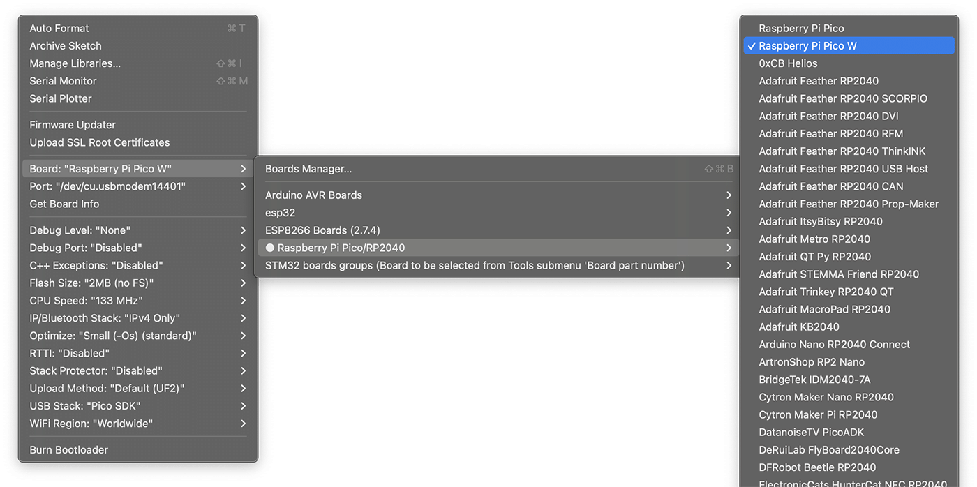
Make sure that the correct Board is selected (It should be Raspberry Pi Pico W):
Then, simply click the Upload button above your Sketch to upload the code from the Arduino IDE to your Pico microcontroller. If it doesn’t work, try changing the port in the Tools dropdown.
Verifying the Code is Running
After the code is flashed your Art-Net/DMX Node should automatically boot up.
The green on-board LED on the Pi Pico W should turn on. This means the device is powered on and the code is running.
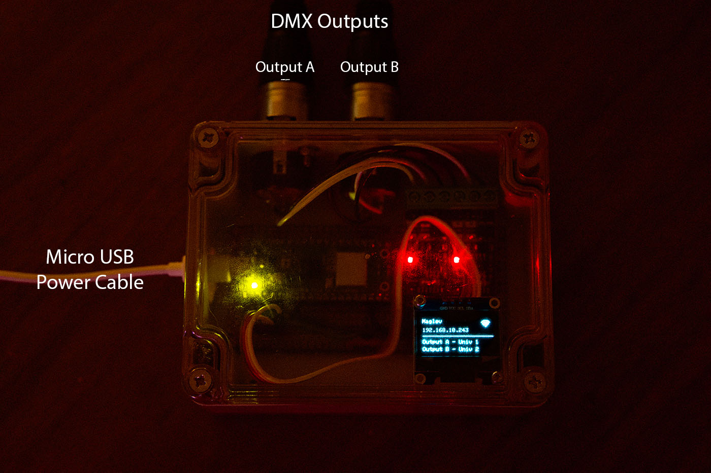
Watch the OLED display to verify your device connects to WiFi successfully and displays an IP Address (exact address is assigned by your router).
The red LEDs on the TTL-to-RS485 Modules should be off because the device is not receiving Art-Net packets.
🎉 Final Result
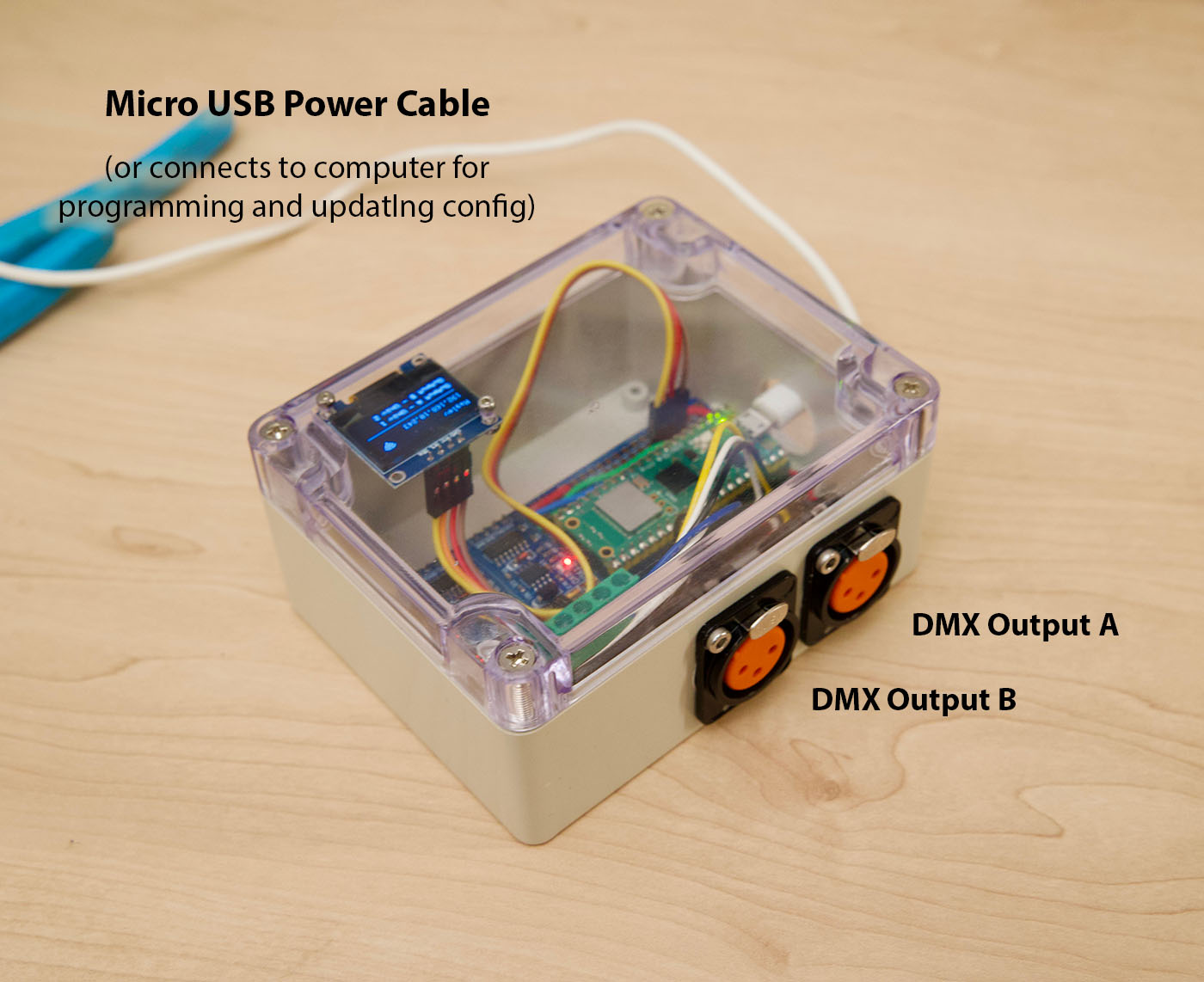
We’re done and it’s ready to connect your DMX lights and the Micro USB power cable:
💡Programming the Lights
There are many options for lighting control software that can broadcast wireless Art-Net over your WiFi network. Reviewing all the options out there is outside the scope of this article.
I’ll focus on the one I choose and use, Lightkey. Lightkey is a powerful piece of software – I’m just starting DMX programming and have only scratched the surface of what Lightkey is capable of.
Lightkey – macOS X Lighting Control Software
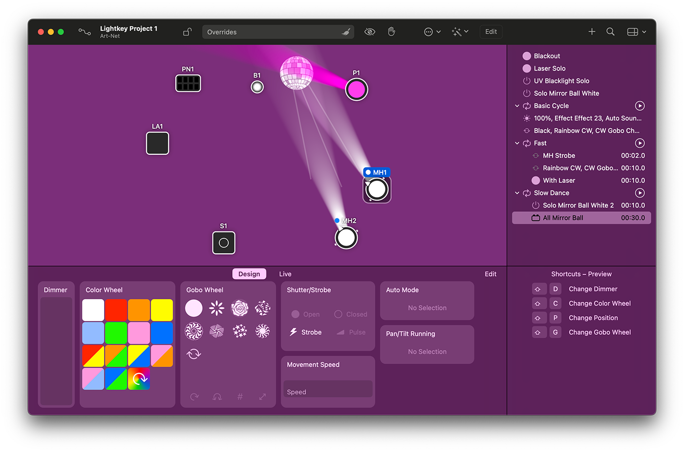
Lightkey is a popular DMX control software for macOS, and it’s known for its intuitive user interface and robust feature set tailored for professional lighting design.
Here are some general observations about Lightkey:
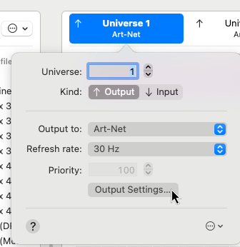
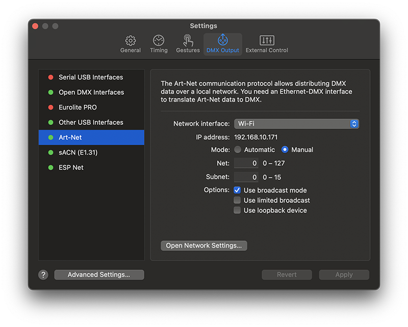
How I Configured Art-Net Output in Lightkey
Lightkey Pros:
- Free version – Only covers 24 channels but enough to at least try it out
- User-Friendly Interface: One of Lightkey’s standout features is its modern and intuitive user interface. This makes it approachable for beginners while still offering advanced features for professionals.
- Integration with macOS: Since it’s designed specifically for macOS, it seamlessly integrates with the operating system, taking advantage of its native features and stability.
- Built-in FX Engine: Lightkey offers a powerful effects engine that allows users to create dynamic, synchronized light shows without the need for complex programming.
- Live Previews: Users can visualize their lighting design in real-time, aiding in design and debugging.
- MIDI Control: Lightkey supports MIDI, allowing users to control their lights using MIDI devices.
- Art-Net and sACN Support: Lightkey supports both the Art-Net and sACN (Streaming ACN) protocols, which are industry standards for transmitting DMX over IP networks.
- Fixture Profiles: The software has an extensive library of fixture profiles, making it easier to set up various lighting equipment.
- Phillips Hue smart lights – Works with Hue bulbs too!
Lightkey Cons:
- Platform Limitation: Lightkey is macOS-only.
- Price: While it offers a free version, greater than 24 output channels requires purchasing a license, which might be too expensive for many users, especially for hobbyists or for small lighting setups.
Lighkey Conclusion:
If possible, trying out the software (perhaps the free version) before committing to a purchase can give you a feel for whether it’s the right fit for your requirements.
5 comments
hi Taylor its awesome work. Could you help me to build micropython version ?
i am interested in the micro python version, do you have one?
Dear Taylor,
thank you very much for this great development and documentation of your build.
I was successfully able to replicate building the DMX ArtNet Interface.
Now I am trying to enhance the system with LAN functionality using a Wiznet W5100S Ethernet Hat, but I am – so far – unsuccessful in achieving a set-up that would allow for dynamically switching between Wifi and Ethernet (i.e. only use Wifi if no valid Ethernet connection is detected).
Have you ever tried to run the setup using a Ethernet-LAN connection?
Best regards,
Mark
Great project! I am interested in a Micropython version.
Hi Taylor,
thank you so much for the cool project. I am thrilled to try it out!
In addition to the DMX out dongles, I would also need a DMX in to ArtNet device, to connect my DMX lightdesk to the Network.
Could you please provide a little help, how to configure the TTL drivers as input?